
pulse-length modulation (PLM, other), used in simple IR remote controls and usually proprietary thingies.pulse-position modulation (PPM), which has a fixed-time pulse separated by variable time pulses for the values (750µs to 2400µs, used in the VEX controllers and by hobby servos, and other various motor controllers).pulse-width modulation (PWM), where the duty cycle of a fixed frequency signal is varied (what the analogWrite() function does).So what I can suggest, if you need something to happen quickly, is looking for the Arduino Servo library and using that to generate the signal to feed the Jaguar.įor future reference, please know that “PWM” is often used to (some would say incorrectly) refer to about three different things: They use pulse-position modulation, which is different.
#Arduino pwm write code#
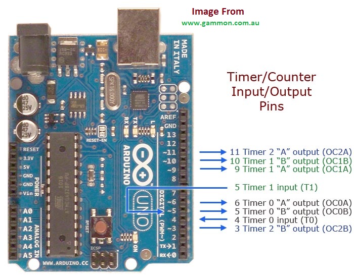
Why? The code I’ve seen to control a hobby servo from the same port you can control a Jaguar from sets up the port the same way, and hobby servos do not actually use “PWM”. If I had to guess, I would say no, the analogWrite() function will not be compatible with the Jaguars. There’s also the robotopen project, which seems to have done work with this. Note that not all Arduino pins have PWM capability, only the pins that have a ~ symbol next to them on the PCB: pins 3,9,10,11 have a PWM frequncy of 490Hz and 5,6 run at 980 Hz.To figure out if the analogWrite() function’s default frequency and range of duty cycles is compatible with the Jaguars or Victors, you will need to read the data sheet and compare to what the Arduino documentation says. I always use capitals with defines to easily distinguish then from variables, for which I use lower case. #define FADE_INTERVAL 50 // ms between fade steps, smaller is faster #define MAX_BRIGHTNESS 200 // max value: 255 #define START_FADE_PIN A5 // input pin, LOW: fade on, HIGH: fade off Configuration values that you can change to your liking After unzipping, move the folder to your Arduino sketches folder. This is task is performed with a timer, using the Arduino’s millis() instruction. To fade it off we gradually decrease the PWM value. To slowly fade the LED on, we have to gradually increase the PWM value. This means we have 255 different brightness steps. The Arduino does not use percentages 0-100, it uses values between 0-255. So … when we set the PWM amount to a value below 100%, the LED will dim. Fade: slowly increase or decrease the PWM value using a timer Because our eyes + brain are too slow to see the switching frequency we perceive this as a lower brightness. If the pulse width is say 30%, the LED will burn 30% of the time and the other 70% it is off.

In stead it uses a method called Pulse Width Modulation: the output is alternated between LOW and HIGH at a high frequency. This name is misleading, the Arduino does not have a digital to analog converter.
#Arduino pwm write how to#
Now … how to fade it? For this we use the Arduino instruction called analogWrite(pin,value). OK, our LED will light when the Arduino output is HIGH, 5V. analogWrite(pin,value), Pulse Width Modulation Click these links for more info on resistors and on Ohm’s law. The formula tells us that with 3.2V, a resistor of 220 ohm will give us a current of around 15mA.

We use Ohm’s law, I = V / R, to calculate the resistor. This means the voltage over the resistor is 5 – 1.8 = 3.2V. For a red LED it is about 1.8V (see the table in this article).

The LED has a voltage drop, which depends on the LED’s color. Most miniature LEDs will light up bright with a current of 10 to 20 mA. What value do we need? Resistor and Ohm’s law to limit the current To accomplish that, we use a resistor in series. We need to limit the current through the LED. A LED acts as an electrical short, which means we can’t connect it directly to an Arduino output or chances are we damage the LED or the output or both. If you’r e not familiar with LEDs yet, this article is a great read.Ĭurrent flows through a LED from + (long wire) to – (short wire). (Click the image to see a larger version.) To experiment with the code, we need to build this little circuit with a LED and a resistor. To do that we’ll use a millis() timer and analogWrite(pin,value) to generate Pulse Width Modulation. This video details one of the elements in the software: how to fade a LED. In the video of an Automatic Fading Kitchen Light we saw that we can slowly fade a LED strip on and off, controlled by an Arduino.


 0 kommentar(er)
